② Define Preventable Range
The UN Regulation (No. 157) shows how to calculate the "preventable" range of scenarios "No. 2", "No. 4", and "No. 5" ※1.This chapter explains the procedure for defining the "preventable" range of scenario "No. 4" based on the UN Regulation※2.
※1 The "preventable" range is listed as "Annex 4 - Appendix 3 Guidance on Traffic disturbance critical scenarios for ALKS" and should be used as a reference.
※2 In the UN Regulations (No. 157), scenarios "No. 2", "No. 4", and "No. 5" are written as "DECELARATION", "CUTIN", and "CUTOUT".
Scenario selection
Go to the "Scenario Database" tab.
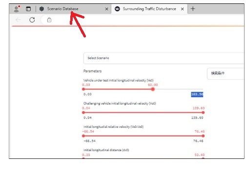
Left-click on the third icon ※ from the top on the left side of the screen.

※ The names and meanings of the icons in the scenario database are listed in the reference.
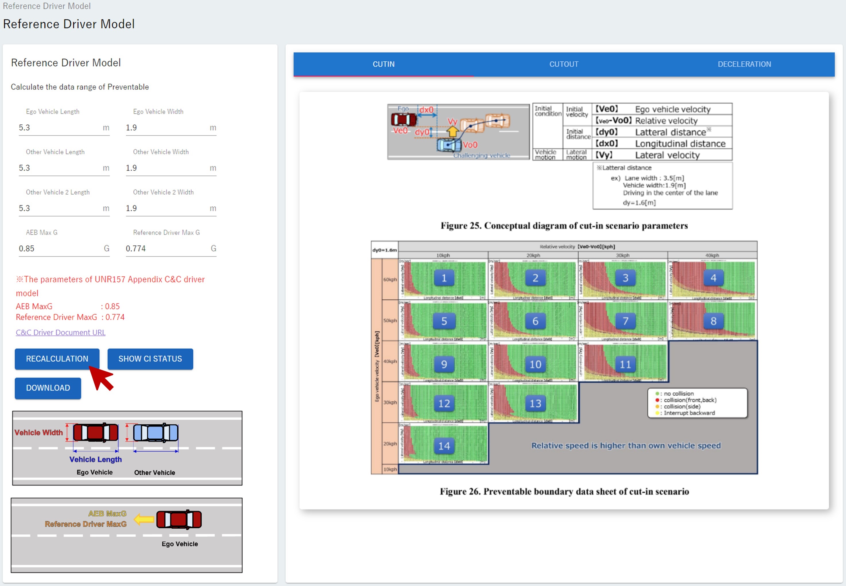
Reference Driver Model screen will be displayed ※.The "preventable" range will be defined through this screen.
※ Reference Driver Model is a model that reproduces the behavior of an exemplary driver. The "preventable" range described in this section is, more precisely, the range that "can be avoided by an exemplary human driver."
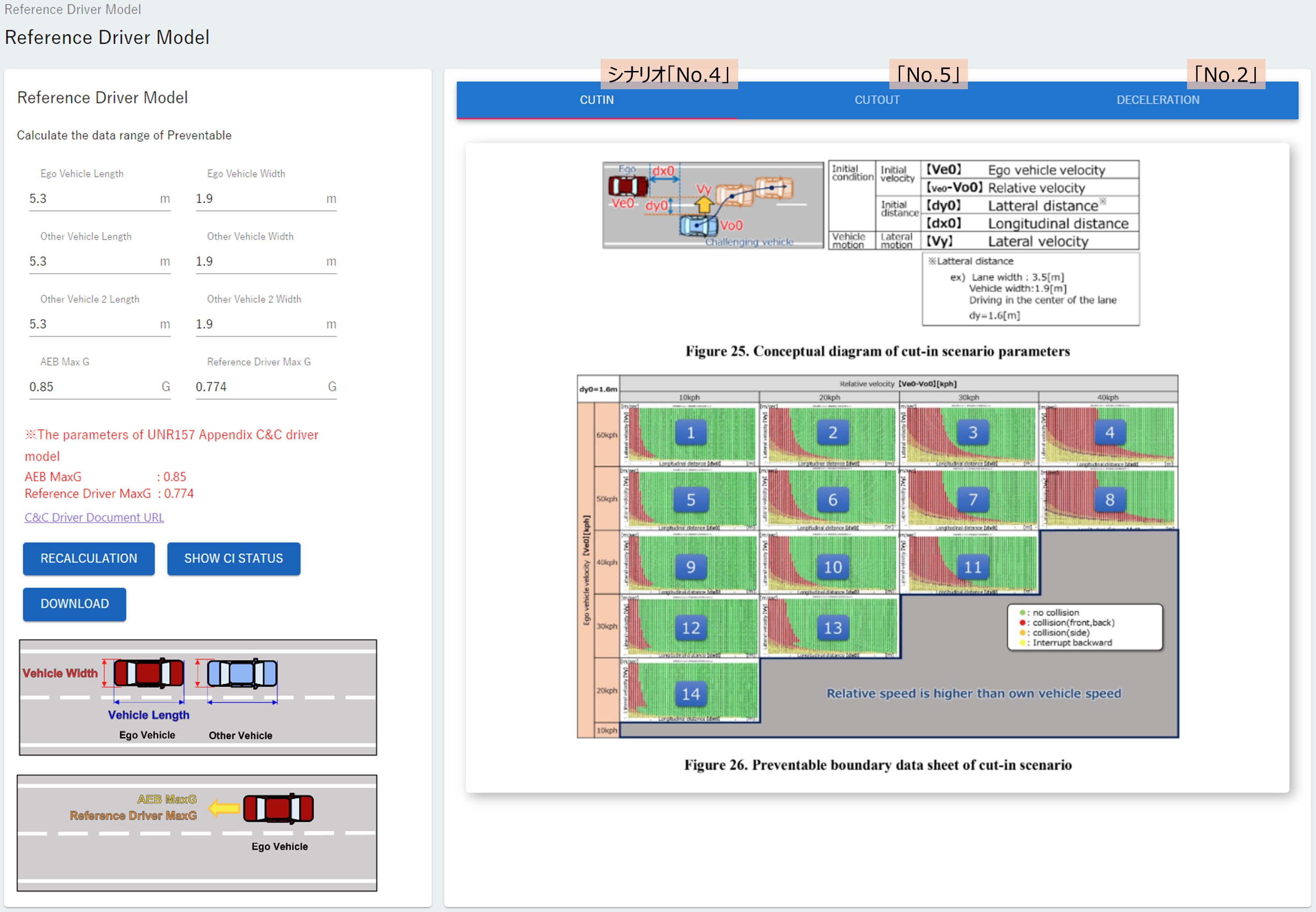
The three selectable scenarios "CUTIN", "CUTOUT", and "DECELERATION" are displayed in the top right corner of the screen. Left-click on the scenario you wish to select ※.In this tutorial, we will explain the scenario "No.4" (referred to as "CUTIN" in this case), so click on the word "CUTIN". A red line will appear below the letters of the selected scenario.
※ Scenario "No.4" is selected by default, so "No.4" will be selected without you having to do anything.
The "Preventable boundary data sheet for cut-in scenario" is displayed in the bottom right of the screen. The multiple graphs displayed in this figure show the "preventable" and "unpreventable" ranges. To explain in more detail, one of the graphs is shown below.
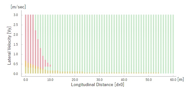
The "preventable" range of scenario "No. 4" is expressed as a two-dimensional range with \(d_{x0}\) (Initial longitudinal distance) on the horizontal axis and \(V_y\) (Maximum lateral velocity) on the vertical axis. The green area is the "preventable" area.
This range is influenced by \(V_{e0}\) (Vehicle under test initial longitudinal velocity)and \(V_{e0}-V_{o0}\) (Initial longitudinal relative velocity).Therefore, we define \(V_{e0}\) and \(V_{e0}-V_{o0}\) multiple times at regular intervals, create a graph showing the "preventable" range for each, and display it on the screen.
The graph shows green, pink, red, orange, and yellow ranges. Their meanings are as follows:
color |
meaning |
|---|---|
green |
non-collision = "preventable" range |
pink |
Front collision of the ego vehicle |
orange |
Side collision of the ego vehicle |
red |
Rear collision of the ego vehicle |
yellow |
The other vehicle going around behind the ego vehicle (reference data) |
Define vehicle size
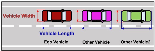
The "preventable" range also changes depending on the size of the vehicle (Vehicle Length x Vehicle Width). The default vehicle size is defined as 5.3[m] x 1.9[m]. If the vehicle sizes of ego vehicle and the other vehicle are different, they must be defined separately. If there are two other vehicles, they are distinguished as "Other Vehicle" and "Other Vehicle 2".
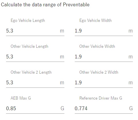
Let's assume that the length x width of the ego vehicle is 4.8[m] x 1.7[m]. Enter the following:
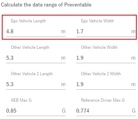
The ego vehicle's body length x width was defined as 4.8 [m] x 1.7 [m].
The vehicle parameters that can be adjusted are as follows:
Parameter |
|---|
Ego Vehicle Lenght |
Ego Vehicle Width |
Other Vehicle Lenght |
Other Vehicle Width |
Other Vehicle 2※ Lenght |
Other Vehicle 2 Width |
AEB Max G |
Reference Driving Max G |
※ The parameters of Other Vehicle2 are not reflected unless Other Vehicle2 appears, as shown below.
Calculate "preventable" range
If you change any parameter, left-click the "RECALCULATION" button.
The "preventable" range for scenario "No. 4" has been recalculated and registered in the scenario database. The calculation results will be used in Example 2:Make evaluation specifications based on the preventable range described later.