③ Make evaluation specifications
This session will explain the procedure for making evaluation specifications based on the "reasonably foreseeable" and "preventable" ranges.
Example 1: Make evaluation specifications based on the reasonably foreseeable range
We will explain the procedure for creating an evaluation specification using scenario "No.4" as an example.
「Scenario Database」Left-click on the fourth icon ※ from the top on the left side of the screen in the "Scenario Database" tab.

※ The names and meanings of the icons in the scenario database are listed in the reference.
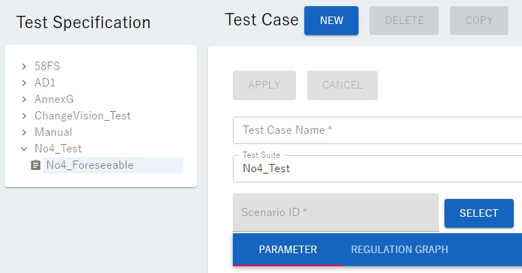
The following screen will be displayed.
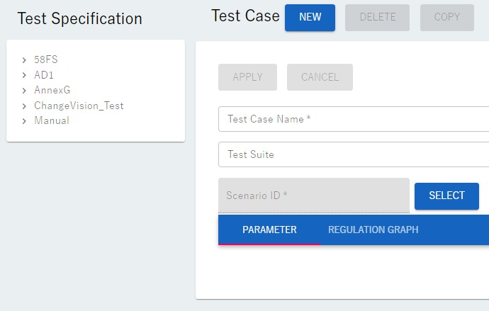
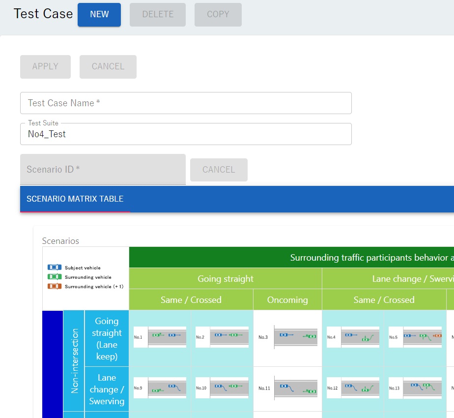
Left-clicking on the "SELECT" button on the screen will display the following screen.
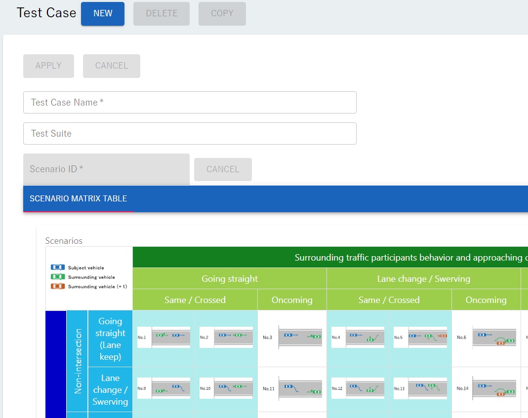
There are 58 scenarios displayed in the "SCENARIO MATRIX TABLE". Left-click on the cell displaying "No. 4" scenario. The following screen will be displayed.
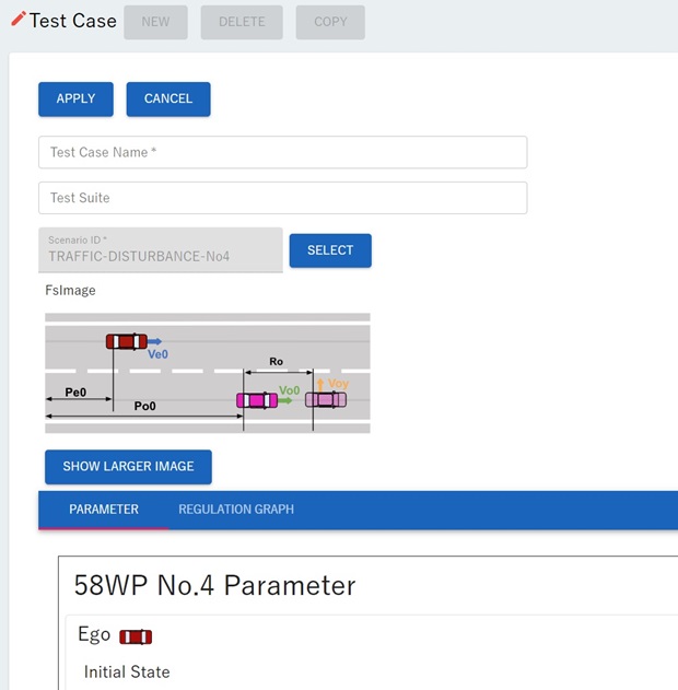
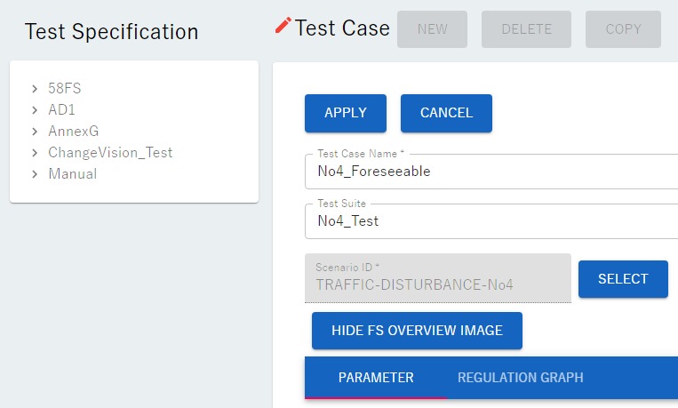
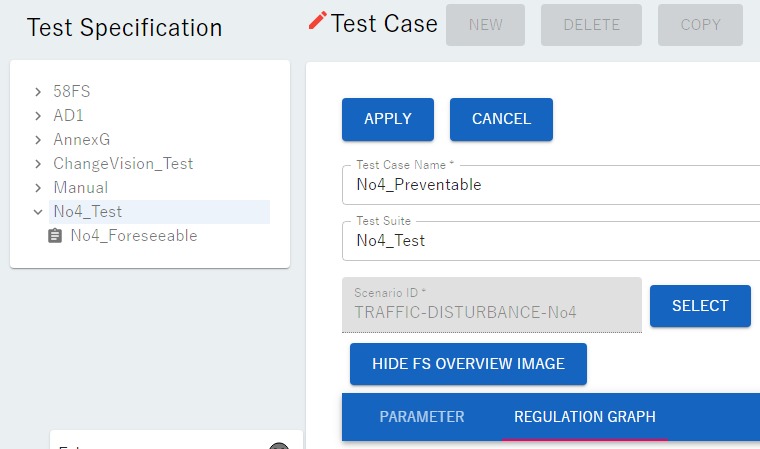
There are "PARAMETER" and "REGULATION GRAPH" buttons. These represent the two methods available for setting evaluation specifications. Left-click on either one. When clicked, a red underline appears under the button. When creating evaluation specifications based on the "reasonably foreseeable range," left-click the "PARAMETER" button. (By default, the "PARAMETER" button is left-clicked.)
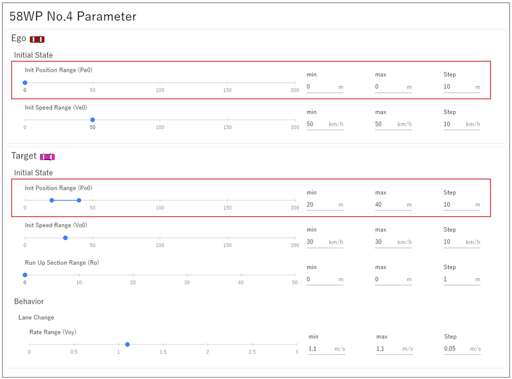
"58WP No.4 Parameter" is shown again below.
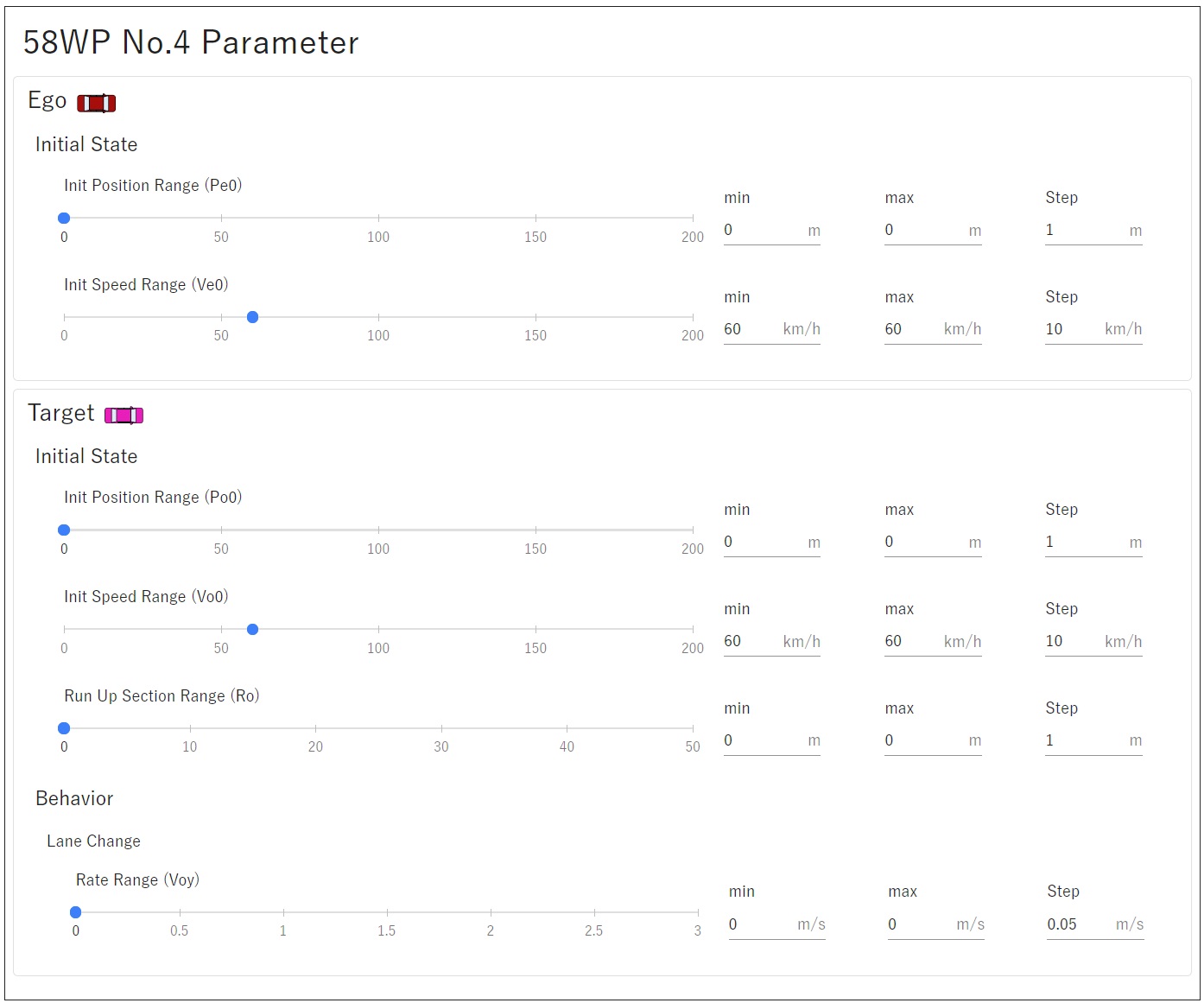
Set the initial states of "Ego" (own vehicle) and "Target" (other vehicle), as well as the minimum/maximum/intervals for "Behavior" (lateral speed when changing lanes).
In ① Define Reasonably Foreseeable Range, we defined the following range as an example of a local range.
Parameter |
Range |
|---|---|
\(V_{e0}\) |
35.25~64.76[km/h] |
\(V_{o0}\) |
16.31~52.50[km/h] |
\(V_{e0}-V_{o0}\) |
5.47~25.73[km/h] |
\(d_{x0}\) |
9.52~60.14[m] |
\(V_{y}\) |
0.28~ 1.71[m/s] |
Note: If you did not close the "Surrounding Traffic Disturbance" tab after defining the "Reasonably Foreseeable Range", you can still access the range you defined from that tab.
The parameter range is set to encompass the "Reasonably Foreseeable Range" as an evaluation specification for autonomous driving. However, in this manual, in order to clearly explain the functionality of the scenario database, we provide the following example with a limited range.
Item |
Meaning |
Minmum |
Maximum |
Step |
Note |
|---|---|---|---|---|---|
Init Position Range ( \(P_{e0}\) ) |
Ego vehicle initial position range |
0[m] |
0[m] |
10[m] |
None |
Init Speed Range( \(V_{e0}\) ) |
Ego vehicle initial velocity range |
50[km/h] |
50[km/h] |
10[km/h] |
None |
Init Position Range ( \(P_{o0}\) ) |
Target vehicle initial position range |
20[m] |
40[m] |
10[m] |
None |
Init Speed Range( \(V_{o0}\) ) |
Target vehicle initial velocity range |
30[km/h] |
30[km/h] |
10[km/h] |
None |
Run Up Section Range ( \(R_{0}\) ) |
Target vehicle run up section range |
0[m] |
0[m] |
1[m] |
Not set |
Rate Range( \(V_{oy}\) ) |
Target vehicle lateral velocity range |
1.1[m/s] |
1.1[m/s] |
0.05[m/s] |
None |
The screen with the above parameters set is shown below. Since \(V_{e0}-V_{o0}\) is determined by the settings of \(V_{e0}\) and \(V_{o0}\), this item does not exist when creating the evaluation specifications.
Additionally, the initial range of vehicle distance in the direction of travel(\(d_{x0}\)),which was a setting item in the FY23 version, is no longer a setting item in the FY24 version. Instead, it is now possible to set parameters for ego vehicle \(P_{e0}\) and target vehicle \(P_{o0}\) as range of initial position.
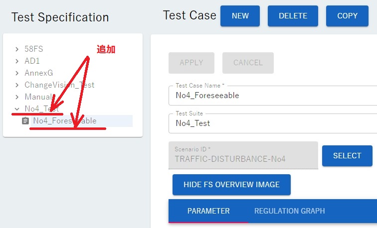
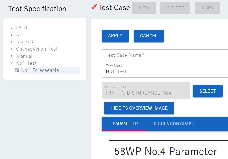
Enter "No4_Foreseeable" as the evaluation specification name (Test Case Name) and "No4_Test" as the storage folder name (Test Suite) as shown below.
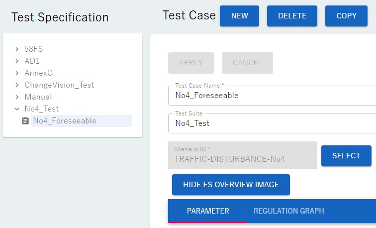
Finally, left-click the "APPLY" button. The evaluation specification "No4_Foreseeable" has been registered as shown below.
This evaluation specification defines a total of three evaluation scenarios. The variables defined for each evaluation scenario are summarized in the table below※.
※ The scenario database assigns each scenario a number starting at 1. In this manual, this number will be called the evaluation scenario number. The evaluation scenario number appears at the end of the name of the OpenScenario file created for each evaluation scenario. This OpenScenario file will be explained in ④ Make and download evaluation scenario files.
Evaluation Scenario Number |
1 |
2 |
3 |
\(V_{e0}\) [km/h] |
50 |
50 |
50 |
\(V_{o0}\) [km/h] |
30 |
30 |
30 |
\(d_{x0}\) [m] |
20 |
30 |
40 |
\(V_{y}\) [m/s] |
1.1 |
1.1 |
1.1 |
Example 2: Make evaluation specifications based on the preventable range.
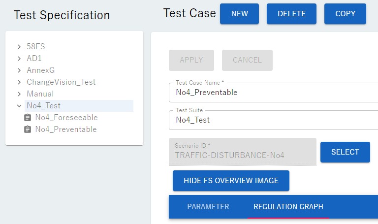
We will explain the steps to create an evaluation specification using scenario "No.4" as an example. On the screen below where the evaluation specification "No4_foreseeable" is registered, left-click the "NEW" button.
The following screen will be displayed.
Left-click on the "SELECT" button and the following screen will be displayed.
There are 58 scenarios displayed in the "SCENARIO MATRIX TABLE". Left-clicking on the cell displaying "No. 4" scenario will display the following screen.
Left-click on the word "REGULATION GRAPH" and the following screen will appear.
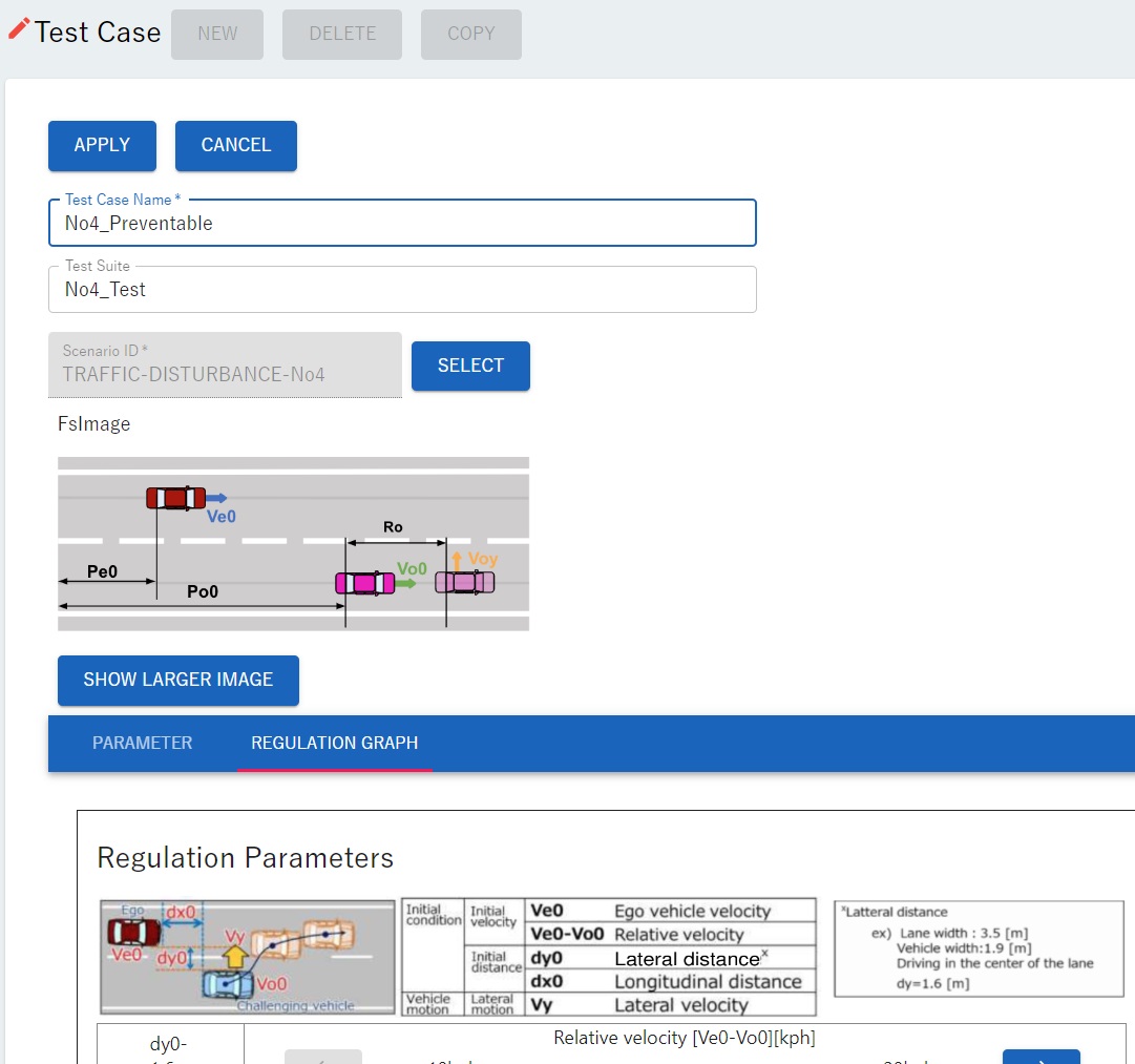
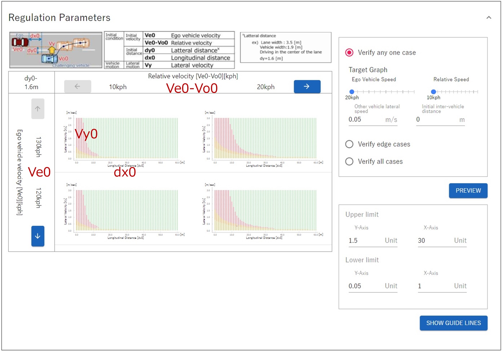
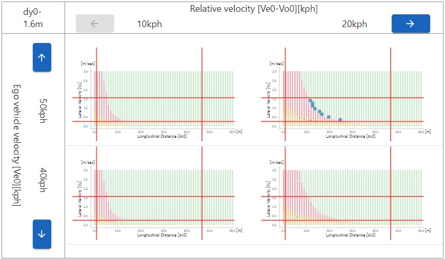
The "Regulation Parameters" section is shown below. Four graphs are displayed in the bottom left of the screen, representing the "preventable" range (green range) ※ and the "unpreventable" range (range other than green). In addition, three options for defining the evaluation specifications are displayed on the right side of the screen: "Verify any one case", "Verify edge case", and "Verify all cases".
※This range is influenced by \(V_{e0}\) (Ego vehicle initial velocity range) and \(V_{e0}-V_{o0}\) (Ego vehicle initial relative velocity based on other vehicle). For this reason, we define multiple \(V_{e0}\) and \(V_{e0}-V_{o0}\) at specified intervals, create a graph showing the "preventable" range/"unpreventable" range for each, and display it on the screen.
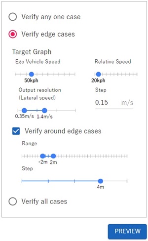
Left-click on the "Verify edge case" circle that appears on the screen. (It will turn into a red circle). "Verify edge case" defines an evaluation scenario for the edge of the "preventable" range, that is, near the boundary between the "preventable" range and the "unpreventable" range.
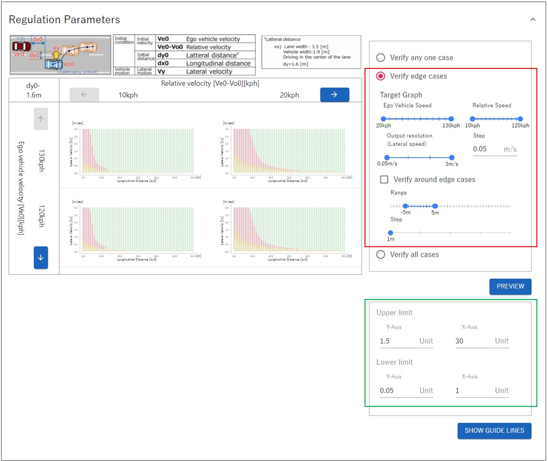
Next, guide lines indicating the range in which the test will be performed are displayed on the graph.
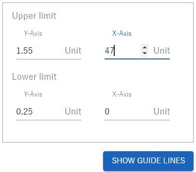
Enter the upper and lower limits for the X-axis and Y-axis that will be the test range in the "Upper limit/Lower limit" designation area (green frame) displayed in the bottom right of the image above. The values to be entered here are \(d_{x0}\)(X-axis) and \(V_{y}\)(Y-axis) from the values output in Define the "reasonably foreseeable" range using probability distribution.
Parameter |
Range |
|---|---|
\(d_{x0}\) |
0.00~46.66[m] |
\(V_{y}\) |
0.28~1.53[m/s] |
When entering values, please use ▲▼ to adjust the values rather than entering them directly.
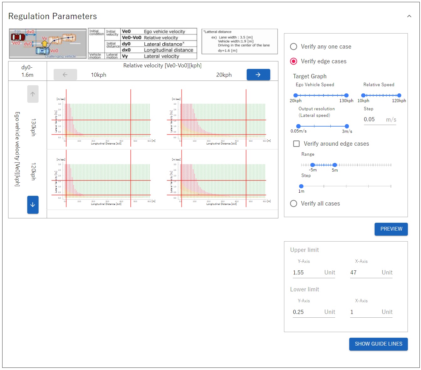
Left-click on "SHOW GUIDE LINES" to display the guidelines.
The next step is to set ranges for the two parameters shown below.
Parameter |
Notation on screen |
Meaning |
|---|---|---|
\(V_{e0}\) |
Ego Vehicle Speed |
Ego vehicle initial velocity |
\(V_{e0}-V_{o0}\) |
Relative Speed |
Ego vehicle initial relative velocity based on other vehicle |
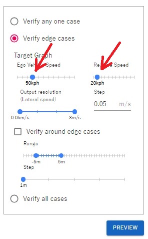
Under "Target Graph" displayed on the right side of the screen, move the "Ego Vehicle Speed" and "Relative Speed" sliders (two blue circles) left and right, adjusting their ranges according to what you want to evaluate. An example is shown below. Evaluation specifications \(V_{e0}\) is 50[km/h],and \(V_{e0}-V_{o0}\) is 20 [km/h]. In this example, \(V_{e0}\) and \(V_{e0}-V_{o0}\) are each set to one point, but you can also specify a range.
Parameter |
Notation on screen |
Specify range using slider |
|---|---|---|
\(V_{e0}\) |
Ego Vehicle Speed |
50~50 |
\(V_{e0}-V_{o0}\) |
Relative Speed |
20~20 |
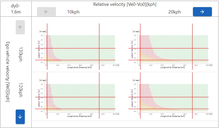
Left-click the "PREVIEW" button. This will superimpose assessment scenarios \([V_{e0}-V_{o0}\) and \(V_{e0}]\) on a graph showing the preventable range (green range)/unpreventable range (non-green range). However, the default setting is \(V_{e0}\) in the top two graphs at 130kph (= 130 [km/h]), and \(V_{e0}\) in the bottom two graphs at 120kph (= 120 [km/h]), so you will need to switch the display.
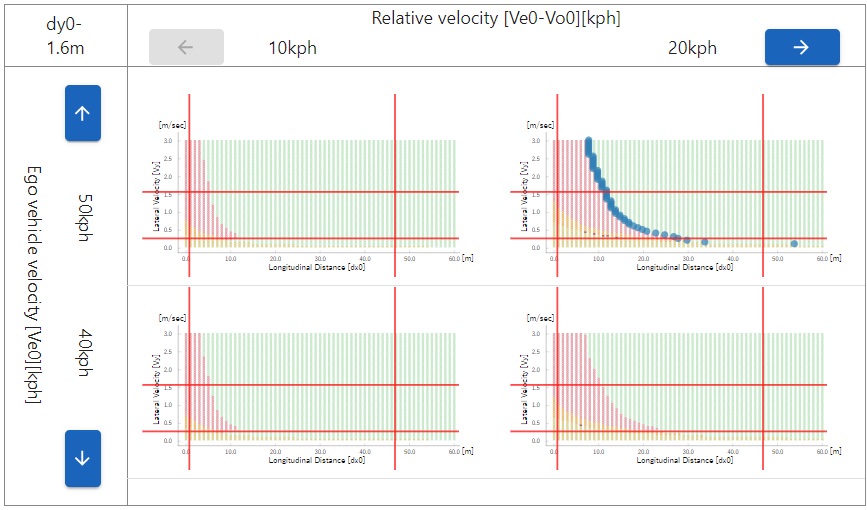
Left-click the down arrow button at the bottom left of the screen several times so that \(V_{e0}\) at the top becomes 50 [km/h]. The down and up arrow buttons change the display range of \(V_{e0}\)※.As shown below, you can see multiple points (blue points) representing evaluation scenarios \([V_{e0}-V_{o0}\) and \(V_{e0}]\) on the graph.
※Similarly, the left arrow and right arrow buttons change the display range of \(V_{e0}-V_{o0}\).
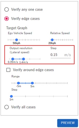
The next step is to set the range and resolution(= the interval that defines the evaluation scenario) of \(V_{y}\). In this tutorial, set it as follows so that it falls within the guide lines.
Setting target |
Setting value [m/s] |
|---|---|
Range |
0.35~1.4 |
Resolution(Step) |
0.15 |
Left-click the "PREVIEW" button. You will see that the number of scenarios in the evaluation specifications has changed as shown below. (A total of eight scenarios are defined, which corresponds to the range and resolution of \(V_{y}\).)
As the final step, we will explain how to set an evaluation scenario offset from the boundary line. Modify the settings on the right side of the screen as shown below. This setting defines an evaluation scenario that is offset by ±2[m] with respect to \(d_{x0}\) from the evaluation scenario set on the boundary line.
Left-click the "PREVIEW" button and the following screen will be displayed.

A total of 16 evaluation scenarios were defined around the boundary.
Enter "No4_Preventable" in the Evaluation Specification Name (Test Case Name) as shown below.
Finally, left-click the "APPLY" button. The evaluation specification "No4_preventable", which defines 16 evaluation scenarios, has been registered as shown below.
This evaluation specification defines a total of 16 evaluation scenarios. The variables defined for each evaluation scenario are summarized in the table below.
Evaluation scenario number |
1 |
2 |
3 |
4 |
5 |
6 |
7 |
8 |
9 |
10 |
11 |
12 |
13 |
14 |
15 |
16 |
\(V_{e0}\) [km/h] |
50 |
50 |
50 |
50 |
50 |
50 |
50 |
50 |
50 |
50 |
50 |
50 |
50 |
50 |
50 |
50 |
\(V_{o0}\) [km/h] |
30 |
30 |
30 |
30 |
30 |
30 |
30 |
30 |
30 |
30 |
30 |
30 |
30 |
30 |
30 |
30 |
\(d_{x0}\) [m] |
23 |
27 |
18 |
22 |
15 |
19 |
14 |
18 |
12 |
16 |
11 |
15 |
11 |
15 |
10 |
14 |
\(V_{y}\) [m/s] |
0.35 |
0.35 |
0.5 |
0.5 |
0.65 |
0.65 |
0.8 |
0.8 |
0.95 |
0.95 |
1.1 |
1.1 |
1.25 |
1.25 |
1.4 |
1.4 |